Laser Fluorination
In the Stable Isotope Lab, laser fluorination is a chemical process wherein oxygen is quantitatively extracted from oxygen-bearing compounds, without isotopic fractionation, and simultaneously converted to diatomic oxygen (O2) gas. This O2 gas may then be analyzed by IRMS to determine its d17O and d18O ratios.
GENERAL STRATEGY:
The laser fluorination line has a REAGENT side and a SAMPLE side, both organized around a central sample chamber. The entire system is kept at high vacuum except for the transient presence of gaseous F-bearing reagent and waste products, the desired O2 sample, and the waste trap when not in use and therefore not frozen. Briefly, a fluorinating agent is introduced into the pre-loaded sample chamber, then the reaction is forced to completion with heat from an infrared laser, and then the O2 gas to be analyzed is cryogenically separated from all of the other gaseous reaction products. If a batch of samples require d18O but not d17O analyses, the O2 obtained may be converted to carbon dioxide (CO2) gas with hot carbon for much higher sample throughput.
Reaction rates at room temperature vary widely, from essentially static for unreactive minerals such as olivine, quartz, or garnet, to sluggish for whole rock powders, to quite fast for water vapor. To speed the reaction along and to ensure it is driven to completion, it is heated to ~1800°C with an 10.6 um infrared (IR) laser.
WHY FLUORINE?
Fluorine has the highest electronegativity of any element including oxygen, and may be thought of as being more oxidizing than oxygen. Electronegativity values at the top end of the scale and descending from there include:
F = 3.98
O = 3.44
Cl = 3.16
N = 3.04
Kr = 2.96, etc.
Thus some fluorine compounds are suitable and used for extraction of oxygen from the samples. Shown here is a balanced reaction for oxygen extraction from the simplest of silicate minerals, quartz, using F2 gas as the fluorinating agent:
SiO2 (quartz) + 2 F2 (g) = SiF4 (g) + O2 (g)
Reagents with highly reactive fluorine include its diatomic (F2) gas, chlorine trifluoride (ClF3), and bromine pentafluoride (BrF5) . We use BrF5 because of its low vapor pressure and because it melts (-61°C) well above the temperature (-196°C) of liquid nitrogen, which facilitates cryogenic separation of the O2 to be analyzed from the other highly corrosive waste products.
A NOT balanced reaction of olivine with BrF5 reagent, depending on various metals in the olivine that may be present, might be:
(Mg,Fe,Ca)2SiO4 (olivine) + BrF5 (g) =>
O2 (g) + (Mg,Fe,Ca)F2 (s) + SiF4 (g) + Br2, BrF, BrF3, BrF5 (g)
After the reaction is complete, LN2 is used to freeze all of the gaseous reaction products EXCEPT O2, cryogenically separating them from the O2 to be analyzed.
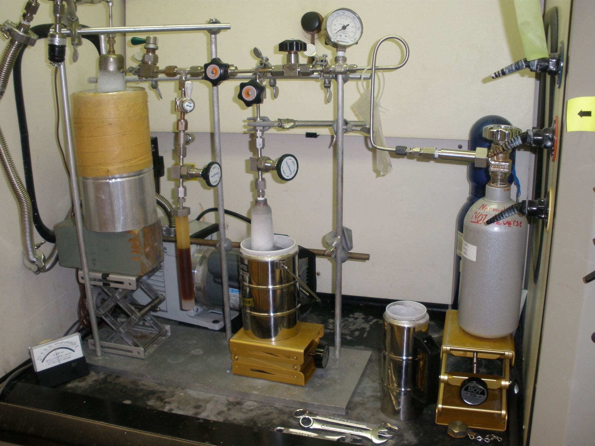
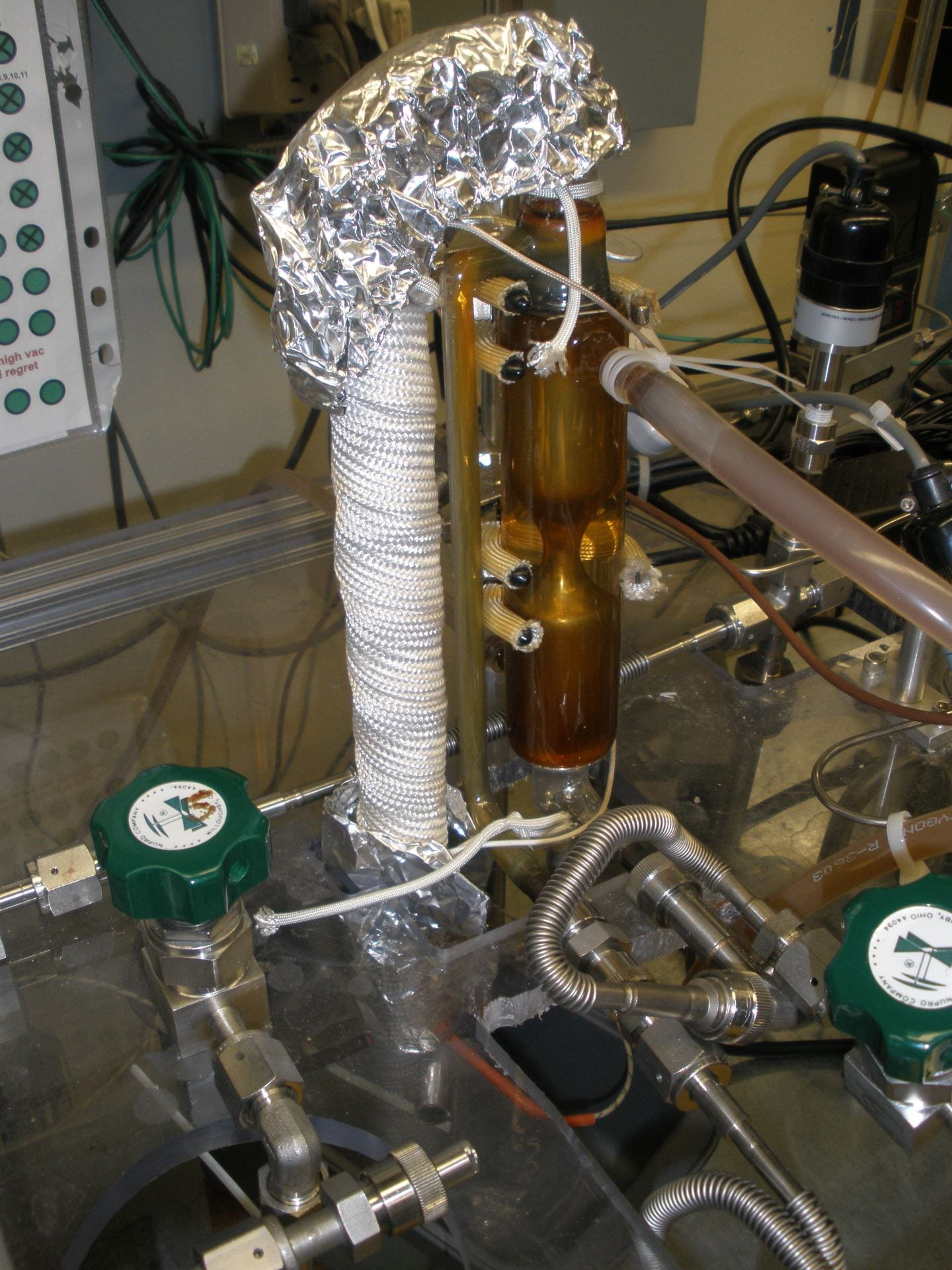
BrF5 reagent before distillation. In the Kel-F plastic vessel toward the bottom left, and showing a coffee color.
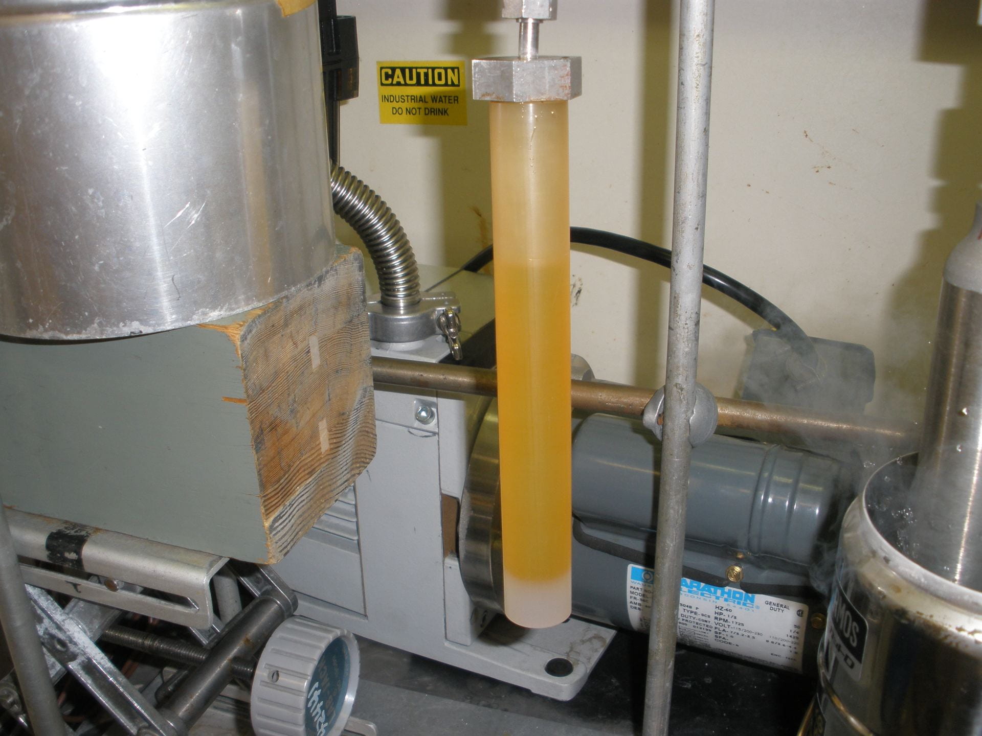
After distillation, the good stuff.
The primary industrial use for BrF5 is in uranium enrichment/isotope separation. In this process, BrF5 is used to produce uranium hexafluoride (UF6) gas from uranium metal. The UF6 gas is further processed by diffusion or centrifugation to separate 235U from 238U, yielding 235U up to and exceeding 97% purity.
Some facts about the laser fluorination line:
– Operates under high vacuum produced with a dual-stage rotary vane vacuum pump backing a synthetic oil diffusion pump, yielding a working pressure on the order of 1.0e-06 torr or less
– Constructed almost exclusively of 316 stainless steel and nickel, it also has a mercury diffusion pump, and a vessel for the electrically heated O2-to-CO2 converter with C from a hot carbon rod, both made of borosilicate glass
– The sample holder is a pure nickel disk ~1in. in diameter with 51 sample holes measuring ~1.3 mm in diameter and ~2mm in depth
– The sample chamber has a barium fluoride (BaF2) window that is transparent to IR radiation from the laser
– The entire surface of the sample holder can be seen with a video camera, and accessed with the camera viewing axis-coincident laser beam, of a New Wave research MIR-10 IR laser
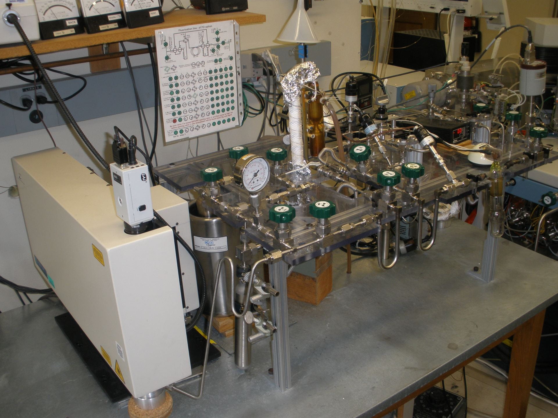
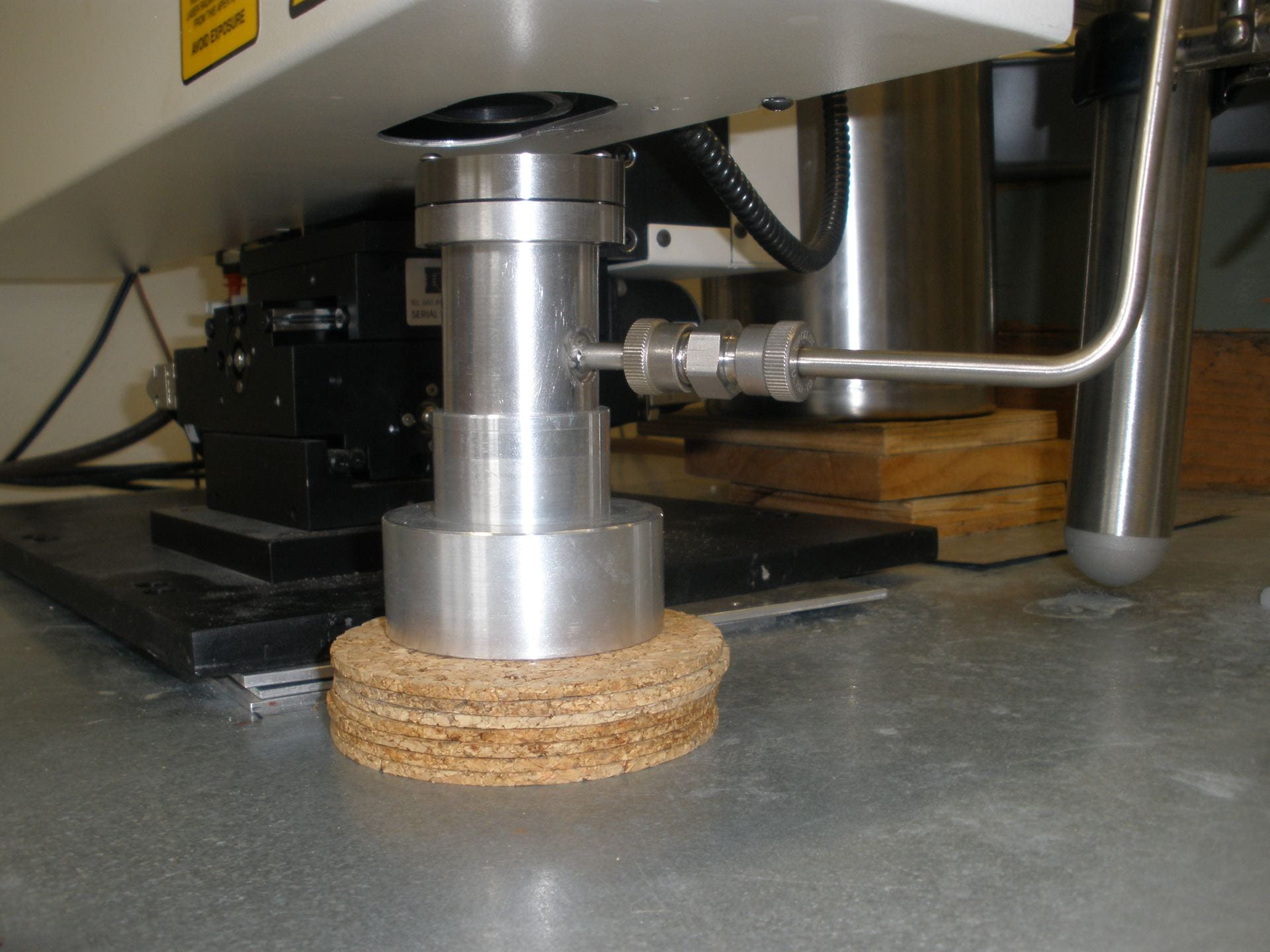
The laser fluorination line. A New Wave Research MIR-10 infrared laser, with its camera on top, is housed in the white cabinet to the left. The bottom of the sample chamber may be seen under it.
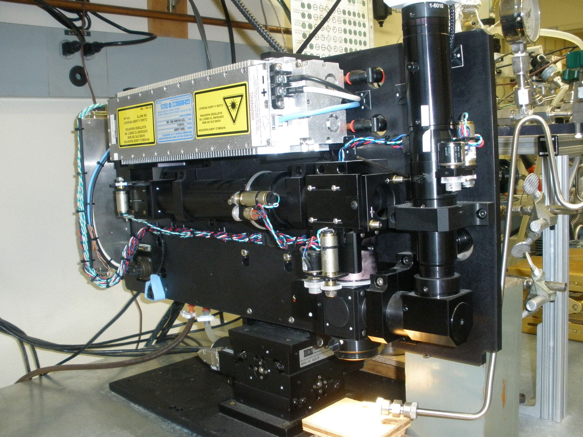
The infrared laser, inside. Note the bit of blue paper labeling tape, thereby defeating the safety interlock.
The mercury diffusion pump.
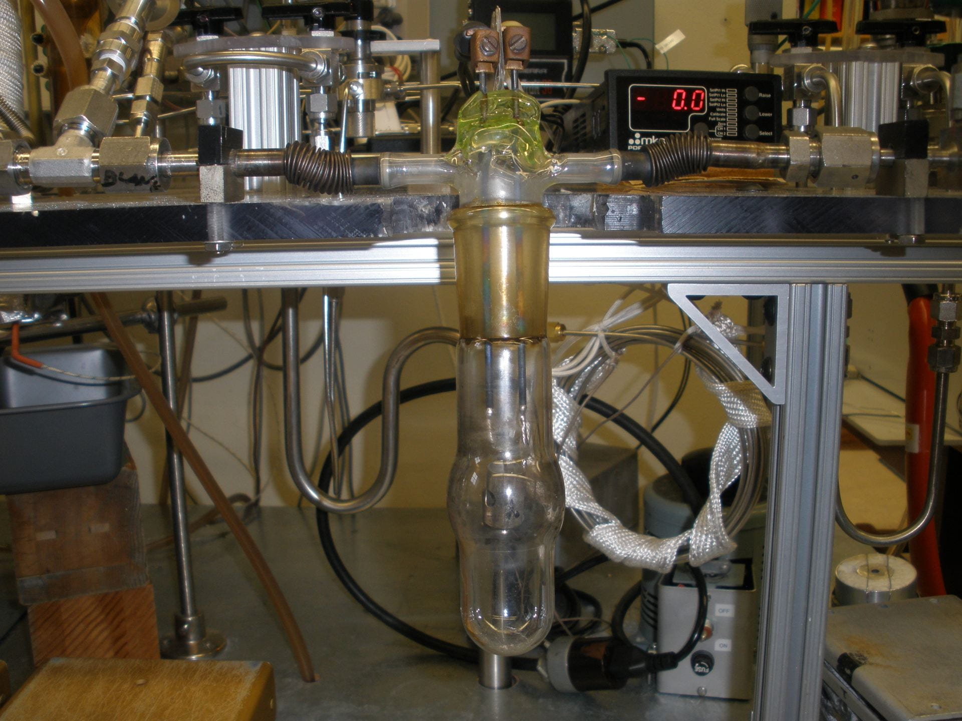
The O2-to-CO2 converter. The small carbon rod is not seen here, and contained inside the platinum heating coil at the bulge near the bottom of the glass.
Some facts about samples and their handling:
– The typical desired mass for samples such as quartz, garnet, or olivine is ~1.5 mg. We balance the needed amount of O2 to be analyzed, with the ability to visually detect unreacted material under the solid waste, and excessive reagent usage. For Mg-rich silicates, glassy fluoride residue may trap and hinder reaction with unreacted material beneath it.
– Some minerals such as quartz or olivine may contain fluid or melt inclusions. These will expand differentially from the mineral under the heat of the laser, and the sample may jump out of its hole or even explode. We either avoid processing samples with these inclusions, or they must be crushed to a finer size.
– Some wt% O2 values for a few minerals
quartz 53.3
albite 48.8
anorthite 46.0
forsterite 45.5
almandine 38.6
zircon 34.9
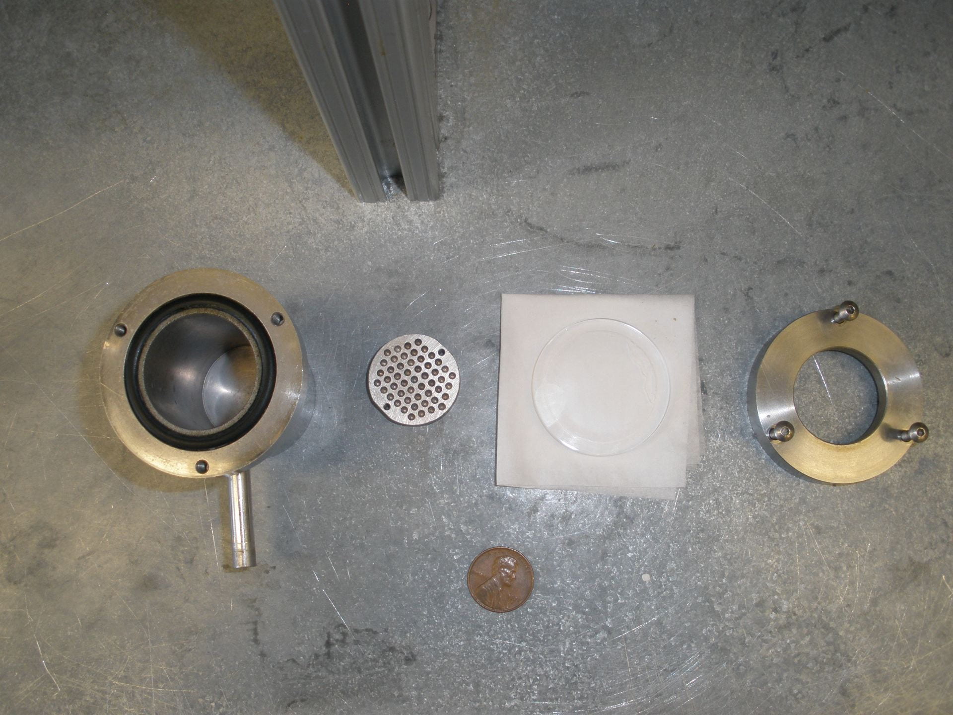
The sample chamber disassembled.
The sample chamber ready for use.
The general sample processing procedure is as follows:
1) The sample chamber is pumped to high vacuum
2) The waste trap on the REAGENT side is immersed in and pre-chilled with LN2, and remains chilled for the entire session
3) A small amount of reagent is put with the samples by freezing it into a loop in the tubing adjacent to the sample chamber, and then isolated. The reagent is then melted and returned to its gaseous state
4) Laser power and movement is controlled by the operator. Power is increased slowly and step-wise so that the mineral does not move or jump while being lased. The laser head is moved by its x- and y-axis motors over the static sample holder. Focusing is controlled with the z-axis motor.
5) Reaction progress is judged by the operator. In general, the reaction produces visible white-violet light. Different minerals emit different amounts of light, but for a single type the light intensity is proportional to the amount of O2 being released. The solid fluoride reaction products e.g. MgF2, CaF2, KF, AlF3, ZrF4, etc., in general are visibly easily discerned from the original sample.
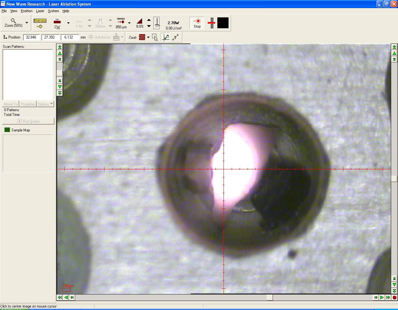
An olivine sample at the start of lasing.
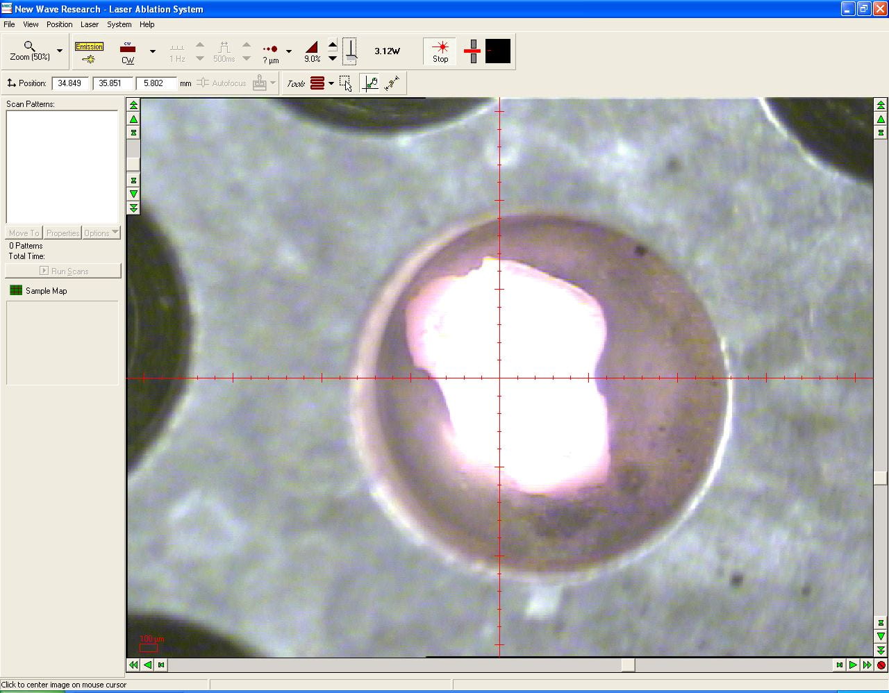
An olivine sample thoroughly enjoying itself.
6) When the reaction is complete, gaseous fluorine compounds are frozen using LN2 at the loop mentioned at step 3), and an additional LN2-chilled loop/trap further downstream on the sample side. The second loop is to trap any traces of F-bearing compounds that escaped the first loop. These F-bearing compounds are highly corrosive, so they are best NOT put it in precision instruments e.g. the MS.
6B) Furthermore, downstream of the the two LN2 trapping loops is a mercury diffusion pump. The purpose of this pump NOT to have any effect upon vacuum. Rather, its purpose is to scrub any remaining traces of fluorine compounds from the O2 sample. As the pump ages after a fresh cleaning, accumulating with time are brownish deposits containing that we speculate to be mixed mercuric fluorides and bromides.
7) The now pure O2 sample may then be collected on molecular sieve for subsequent purification by gas chromatography (GC) and then analyzed for its d17O and d18O values, OR it may be passed to the hot carbon O2-to-CO2 converter and then analyzed for d18O only. Conversion to CO2 allows for much faster point-to-point transfer of the sample using only LN2 and no molecular sieve, and this yields much higher sample throughput.
8) At this point the sample side is isolated by valve(s) from the sample chamber. The valve between the first loop with sample chamber, and the waste trap, is opened and the loop is heated; the waste reagent and SiF4 will then freeze in the waste trap. The second loop/trap collects far less waste; it remains frozen for the entire session and is cleared at the end of the day.
Airlock Sample Chamber
In using the standard sample chamber described above, a general requirement is that the reaction rate at room temperature must be essentially static. A good measure of how reactive the samples are, is the result from measuring an analytical blank. The process of acquiring a blank is exactly the same as acquiring a sample, but without application of the laser. In essence, all of the sample and standards within the chamber are allowed to react with the reagent at room temperature for five minutes.
Given that samples commonly yield ~25 umol of gas, the blank must be less than 1.0 in order to proceed. In general, the blank is preceded by several pre-treatments lasting longer than five minutes. The purpose of these pre-treatments is to remove any reactive materials that are not part of the samples or standard. The most common example of these is water molecules adsorbed to the chamber’s inner surfaces, that pumping with a high vacuum system will not remove.
Some samples react too quickly to be analyzed using the regular chamber. As the sample to be analyzed is being lased, other samples within the chamber also contribute their own oxygen in an phenomenon commonly referred to as crosstalk.
The resolution to this issue is the use of an airlock sample chamber. Therein, all of the samples are isolated from the laser chamber. Using sliding rods, samples and standards are picked one at a time form the rotating carousel, and passed through the isolation valve into the laser chamber. The design is similar to and modeled after the airlock loading systems found on (much) older scanning electron microscopes.
Some examples of materials the react quickly enough so that the airlock is required: whole rock powders, k-feldspar esp. sanidine, clay minerals, any organic material e.g. mummy shroud fibers, etc.
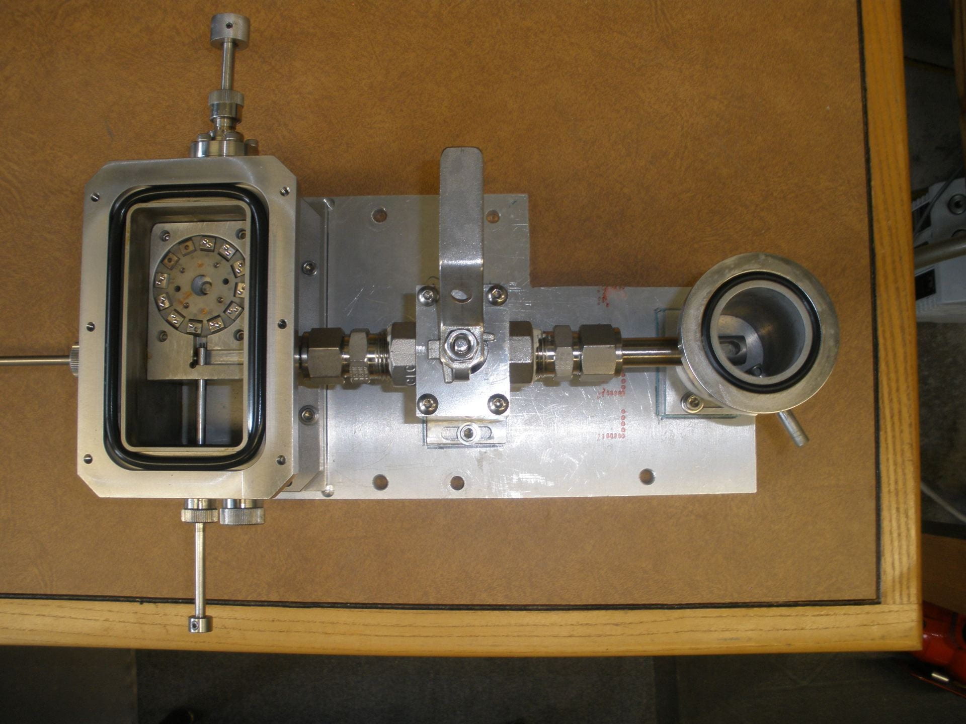
Airlock sample chamber.
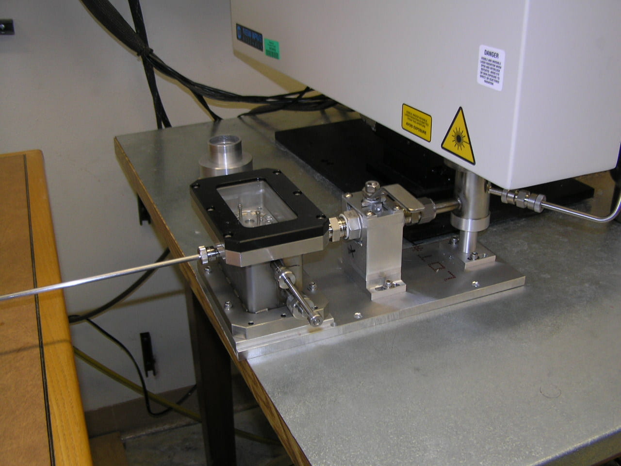
Airlock sample chamber.
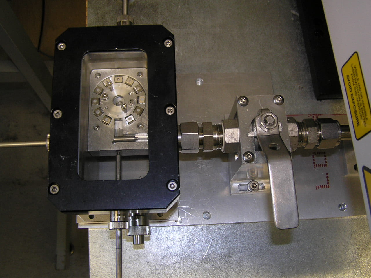
Airlock sample chamber.
– JP